
It’s purpose is to avoid that the LED and ground are directly connected to the power supply. An NMOS transistor is on when a 1 is present at the gate terminal.ĭon’t be confused by zigzag-shaped component at the power supply. Start the simulation in the circuit below and observe how the switch on the gate input turns the transistor on and off. If the transistor is off, the source/drain path is interrupted. When the transistor is on, signals can flow along the source/drain path. The signal at the gate terminal determines whether the transistor is on or off. MOSFETs have three terminals, labeled “Gate”, “Source” and “Drain”. However, as we will see below, they show their true power when transistors of both types are combined. Both types can be used individually to build logic gates. There are two different types of MOSFET transistors: NMOS (n-type MOS) and PMOS (p-type MOS). It is only important to know that a transistor is an electronic switch. What this exactly means is not relevant for this tutorial. Nowadays, computers mainly use so-called “MOSFET” (Metal-Oxide-Semiconductor Field-Effect Transistor). There are many different types of transistors.
#Transistor diagram for a nand gate manual
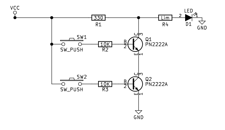
Unlike manual switches, which are operated by hand, electronic switches can be controlled by an electrical input signal. Transistors are electronic components that are essentially switches. Logic gates are constructed from so-called “transistors”. Move the mouse over the NAND gate to display the truth table of the NAND gate.īut how does a NAND gate work inside? Transistors Start the simulation and press different combinations of the two switches to observe which combinations make the LED light up. A modern microprocessor like the one in your smartphone contains billions of logic gates.Īn example of such a gate is the NAND gate shown in the circuit below. The circuit was built and tested at 4.8 volts DC (4 AA NiMH rechargeable batteries).The heart of every computer consists of logic gates that perform the basic logical operations necessary to run programs.This resistor is shown in the schematic as a resistor with the value “Lim” for completeness. The LEDs used in the project have a built in current limiting resistor eliminating the need for an external resistor to protect the device.

(All parts for the project are available in our store.)


 0 kommentar(er)
